Motor Protection Filters limit peak voltage.
Press Release Summary:
Placed at output of drive, KLC Series V1000 Filters protect both motor and cable runs. Units limit motor terminal voltage to 150% of bus voltage when applied to output of VFD and ahead of motor connected with up to 2,000 ft leads depending on carrier frequency and lead type. Filters minimize motor heating, noise, and vibration, as well as reduce common mode current by 30%, slowing down rate of change of PWM switching as seen by load.
Original Press Release:
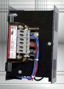
KLC-Series Motor Protection Filter
V1000 KLC-Series Filters provide Superior Protection for Motors. The latest addition to the KLC-Series has a smaller mechanical layout, but provides a high level of performance. The V1k limits peak voltage, increases voltage rise time, and reduces common mode current by at least 30%.
Milwaukee, Wisconsin, June 29, 2005
Peak Voltages on a 460V system can reach 1200 to 1600 V, causing rapid breakdown of motor insulation, leading to motor failure. On 575 V systems, the peak voltages can easily reach 2100 V. If this is left uncontrolled, insulation failure may occur. The same peak voltages that damage the motor can also damage the cable. Since the V1000 filters are designed to be placed at the output of the Drive, these units will also protect the cable runs.
The added inductance of a V1000 filter will also help reduce motor heating, motor noise, and motor vibration by reducing the current harmonics in the system.
Filtering increases motor life. The V1000 reduces common mode current by at least 30%. The V1000 substantially slows down the rate of change of the PWM switching as seen by the load. The slowing of the rate of change of the PWM switching increases the capacitive coupling impedance between bearings and bearing races. The increase in capacitive coupling, in turn, reduces the damaging Common Mode Currents and increases motor up-time. The V1000 reduces bearing, pitting, and fluting.
The V1000 is guaranteed to limit motor terminal voltage to 150% of bus voltage (peak input voltage) when applied to the output of a VFD and ahead of a motor connected with up to 2000ft leads depending on carrier frequency and lead type and following the manufacturer's guidelines. The V1K must be sized at no more than 110% of the drive output current rating. Additional restrictions apply for multiple motor applications, consult factory. The V1K must be sized to have regular line current loading of no less than 25% of its current rating. If the load has a potential for overhauling the drive must be equipped with braking resistors or other features limiting bus voltage to no more than the level of the peak line voltage. The V1K must be wired no more than 12 feet from the drive.
Voltage wave reflection is a function of the voltage rise time (dV/dT) and the length of the motor cables. The impedance on either end of the cable run does not match, causing voltage pulses to be reflected back in the direction from which it arrived. As these reflected waves encounter other waves, their values add, causing higher peak voltage. As wire length or carrier frequency increases, the overshoot peak voltage also increases. The V1000 Motor Protecting Output Filters have been designed to limit peak voltage and increase voltage rise time. In specific applications, the V1000 has performed with cable runs of up to 3,000 feet.
TCI is committed to developing and utilizing operating systems and technologies that ensure TCI consistently satisfies each customer's quality and service needs while meeting all industry, statutory, and regulatory standards.
For more information on V1000 KLC-Series Motor Protection Filters, please feel free to visit our website at www.transcoil.com or contact us at (800) TCI-8282.
TCI will be the supplier of choice for products and services that increase the value and improve the performance of electronic power conversion systems.