Architectural Documentation of Building Facades
Renovating buildings involves producing architectural documentation. To do this, laser scanning is a fast and a reliable solution. For the Northwestern Mutual Life building, laser scanning achieved this in 4 days rather than
several months using a traditional method. The process was also instrumental in detecting the difference between
what was actually built and the original plans.
Renovating historical landmarks requires a careful balance between preserving the architectural elements that
characterize the generation of the original build while updating items to support modern life. Thus was the burden
consultants faced when designing plans for a $30 million restoration of the Northwestern Mutual Life building in
Milwaukee, WI.
Constructed in 1914, the Marshall & Fox-designed neoclassical building on Wisconsin Avenue boasts ten 74-foot
high, 422-ton columns with Greek Corinthian treatments, and is crowned by a majestic granite cornice. Restoring
the cornice was key to the historical preservation of the building.
Having been built before the age of computers and CAD programs, the first step of the restoration required
obtaining digital as-built documentation of the cornice. Local consulting firm, SightLine, LLC, was charged with the
task of gathering the measurements from the center points along the cornice of the building.
SURVEYING FROM AFAR
Bridging the gap between innovation and tradition, SightLine utilized Laser Scanning technology to generate the
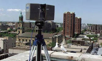
measurements necessary to restore the classic beauty. Sightline collected the measurements with the FARO Laser
Scanner LS 880.
The Laser Scanner LS builds a 360-degree point cloud of a scanned surface by sending an infrared beam into the
center of a rotating mirror. This deflects the laser around the environment being scanned. Using encoders to
measure the mirror rotation and the horizontal rotation of the Laser Scanner, the X,Y,Z coordinates of each point
can be registered and modeled.
Sightline completed the survey of the cornice in four days. The Laser Scanner afforded Sightline the luxury to
safely collect the scans 150 feet away, within an accuracy of 1/8 in. All measurements were completed without
erecting any scaffolding or dropping swing stages over the side of the building.
»Almost all of the data was collected from the ground,» Anstey observed. »The contractor seemed to think the
equipment was magic because it could produce a point cloud view as fast as it was being scanned.»
Sightline overcame any line-of-sight issues by strategically placing registration spheres or targets around the
scanner and the building. The scans were taken from different viewpoints on the ground and roof top and linked by
the spheres within the Scene software.
The clear-view representation of the linked information produces a visualization similar to that of an x-ray. The
effect left the contractor with the impression that the Laser Scanner LS could scan through walls.
THE DATA
Sightline selected portions of the 3-D point clouds, and through viewing the cloud in various directions, they traced
the items in AutoCAD Architectural Desktop to generate line drawings. They produced 16 sets of digital 2-D
drawings of the cornice and building profile. The scans revealed that the original design drawings did not match
what was actually built. An entire wing of the structure extended out further than the other, something that was not
noticeable to the human eye.
Once the contractor saw the detail generated by the scans, he requested additional information about the building.
Sightline provided elevation studies and details on sections through typical areas (such as window bays) and
ornamental architectural elements. More deviations were discovered. While the existing drawings documented
finials as stylized acorns, the scans revealed that they were actually barley hops.
Sightline was able to provide the information without revisiting the actual site, due to the immense amount of data
collected during the initial scanning. The Laser Scanner LS captures 120,000 measurement points per second,
therefore, generating the additional information was only a matter of software management.
OLD VERSUS NEW
The rapid rate of collection, ease of data capture, and accuracy of measurements were major factors that
influenced Sightline to employ laser scanning techniques versus traditional survey methods.
»Using the former method to gather measurements could have taken months, considering that a large amount of
scaffolding would need to be erected,» stated Anstey. »Not to mention the fact that if workers had missed anything,
they would have to keep going back to the site to collect data. And who is to say that the data would have been
accurate?»
Speed and efficiency were great benefits for the contractor. The rapid scanning process allowed his crew and
subcontractors to focus on other parts of the project to avoid delays.
»What is unique about this project is that the contractor who hired us to do the work had never used this type of
technology before,» Anstey observed.
Laser scanners operate with a literal click of a button. The scan data displays simultaneously with the scanner´s
rotation. Once the scan is complete, the user can navigate the scan in 2-D and 3-D views, essentially flying through
the point cloud data. A quick view displays a spherical view from the scanner´s perspective and allows operators to
make basic measurements within the scan.
THE TECHNOLOGY
Laser Scanning is fast emerging as a preferred method of obtaining as-built documentation. The Laser Scanner LS
uses Phase Shift technology, as opposed to time of flight distance recording. The main advantage of Phase Shift is
speed - up to one hundred times faster than time of flight.
With Phase Shift technology, instead of a single pulse being reflected and the time of flight being measured,
constant waves of varying length are projected. Upon contact with an object they are reflected back to the scanner.
The distance from the scanner to the object is accurately measured by surveying the phase shifts in the waves of
infrared light.
The Laser Scanner LS splits the laser beam into three component parts operating on three different modulation
lengths: 76m, 9.6m and 1.2m. The distance of the reflecting object from the scanner is determined by identifying
the exact reflection point in the 1.2m cycle. The use of three varied ranges means a higher degree of accuracy can
be achieved over a greater distance as the specific range of the target can always be measured using the finest
1.2m range.
AREAS OF APPLICATION
Sightline has expanded its service offering by employing laser scanning technology - from creating floor plans for
buildings without documentation to providing dimensions of structural columns.
»We scanned a column that was the main support of a building,» Anstey recalls. »The column was failing and the
customer needed to have a new marble column cut to replace it.»
Rather than using a tape measure to obtain the column´s subtle changes in diameter along its length, SightLine
scanned the column and presented to customer with the data required to have the column duplicated to the exact dimensions.
The areas of application for the Laser Scanner LS do not stop with Civil Engineering. The technology has been
applied to Asset Management, Forensics, Heritage and CGI programming. The ability to conduct virtual
walkthroughs - be it in a nuclear facility or on a crime scene - is a particular area of growing interest among
businesses.
Laser Scanner operations are contributing to the ultimate safety of occupational environments. Additional
innovations have made laser scanners even more user friendly. Operators of the FARO Laser Scanners, for
example, can now control the device through PDA´s and iPods®. The scanners can also function on base-mounted
batteries, alleviating the need for dangerous cabling.